
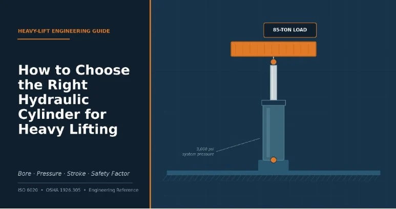
The right hydraulic cylinder for a heavy lift is the one sized to your calculated load and working pressure — not the one with the biggest number on a spec sheet.
Pick a cylinder on gut feel or a catalog default and you end up in one of two places: overpaying for tonnage you’ll never use, or undersizing the bore and finding out mid-lift that a rod is bending, a seal has blown, or a hose fitting has let go. Neither is a place you want to be with a load in the air.
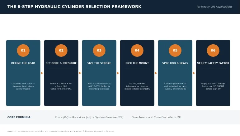
This guide walks through the same process a fluid-power engineer runs on a heavy-lift job: calculating the real load, matching bore to working pressure, sizing stroke and mounting, specifying rod and seals, and applying the safety margins that OSHA and ISO expect on a compliant lift. There’s a working force-reference table and a six-step selection framework you can pull straight into a spec sheet.
What a Hydraulic Cylinder Actually Does
A hydraulic cylinder is a linear actuator that converts pressurized fluid into push or pull force, using a piston inside a sealed barrel to drive a rod in and out. Every decision in this guide comes back to that one relationship: piston area times system pressure equals the force you actually get.
Two design types cover most heavy-lift work:
- Double-acting cylinders — powered in both directions, which is what you want anywhere a load has to be lowered under control rather than dropped — cranes, presses, lifting gantries.
- Single-acting cylinders — powered one way and returned by gravity or spring, common on dump beds, basic jacks, and lower-cost jacking rigs where controlled descent isn’t a requirement.
Barrel construction matters just as much:
- Tie-rod cylinders — bolted-together construction that’s straightforward to rebuild in the field — the default for most mobile and industrial equipment.
- Welded-body cylinders — a smaller footprint and higher pressure tolerance, at the cost of being harder to service without sending the unit out.
- Telescopic cylinders — multiple stages nested inside one another, used whenever you need long travel from a short retracted length, as on dump trailers and aerial platforms.
Get this first call wrong and every spec downstream — bore, seals, mounting — ends up fighting the application instead of working with it.
Step 1: Calculate the Actual Load Before You Spec Anything
Start from the true worst-case load, not the average one — static weight, plus dynamic or shock loading, plus a margin for how unevenly that load will be shared if more than one cylinder is doing the lifting.
- Static load — the dead weight of the object, plus any fixtures, attachments, or rigging hardware moving with it.
- Dynamic / shock load — sudden starts, stops, wind, or an off-center pick all add force beyond the static weight; heavy-lift practice typically builds in a shock allowance on top of the calculated static load rather than sizing to the static figure alone.
- Multi-cylinder load share — don’t assume a perfectly even split. If the lift point isn’t dead-centered, one cylinder can momentarily carry well over its “equal share” of the total load — size each cylinder for that worst case, not the average.
This number — not the cylinder’s maximum rated tonnage — is what every later step gets measured against.
Step 2: Match Bore Size to Your Working Pressure
Bore size and system pressure are two sides of the same equation, so once Step 1 gives you a target force, you either fix the pressure and solve for bore, or fix the bore — because of space constraints — and solve for the pressure you need.
Force (lbf) = π × (Bore Diameter ÷ 2)² × System Pressure (psi)
Mobile and construction equipment typically runs 2,000–3,000 psi; stationary industrial systems often run up to 5,000 psi; specialized high-pressure press and jacking systems can run higher still. Higher pressure lets you use a smaller, lighter cylinder for the same force, but it also raises wear on seals, hoses, and fittings — which is why pressure and bore are chosen together, not in isolation.
Cylinder Force Reference Table
The table below is calculated directly from the bore-area formula above across the pressure bands most heavy-lift systems run at, so you can sanity-check a spec without opening a calculator on-site.
| Bore Diameter | Piston Area (in²) | 2,000 psi | 2,500 psi | 3,000 psi | 3,500 psi |
|---|---|---|---|---|---|
| 2″ | 3.14 | 3.1 t | 3.9 t | 4.7 t | 5.5 t |
| 3″ | 7.07 | 7.1 t | 8.8 t | 10.6 t | 12.4 t |
| 4″ | 12.57 | 12.6 t | 15.7 t | 18.8 t | 22.0 t |
| 5″ | 19.63 | 19.6 t | 24.5 t | 29.5 t | 34.4 t |
| 6″ | 28.27 | 28.3 t | 35.3 t | 42.4 t | 49.5 t |
| 8″ | 50.27 | 50.3 t | 62.8 t | 75.4 t | 88.0 t |
| 10″ | 78.54 | 78.5 t | 98.2 t | 117.8 t | 137.4 t |
| 12″ | 113.10 | 113.1 t | 141.4 t | 169.6 t | 197.9 t |

Step 3: Size the Stroke Length — and Watch for Rod Buckling
Stroke should match your actual travel distance plus roughly a 10–15% buffer for mounting and alignment tolerance — but on long strokes, rod diameter, not bore, is usually what limits how much load the cylinder can safely carry.
An extended rod behaves like a slender column under load: push it too far out relative to its diameter and it can buckle sideways well below the cylinder’s rated force. Long-stroke heavy-lift cylinders typically need an oversized rod, a stop-tube to limit how far the piston travels toward the rod-end bearing, or both. This is one of the most common reasons a cylinder that’s “rated high enough” on paper still fails in service — the bore was sized for the load, but the rod wasn’t sized for the stroke.
Step 4: Choose a Mounting Style That Matches Your Force Direction
The mounting style has to keep force traveling straight through the cylinder’s centerline, because side-loading the rod is the single most common cause of premature seal and bearing wear.
- Tie-rod / foot mount — bolted along the barrel, simple and strong, best where the mounting surface is rigid and well-aligned.
- Clevis mount — a pin joint at the rod and/or cap end, letting the cylinder pivot as the load’s geometry changes through the stroke — common on booms and lift arms.
- Trunnion mount — pivots on trunnion pins at the cylinder’s midpoint, which handles side loads from angular movement better than a simple clevis.
- Flange mount — a flat plate bolted to a fixed structure, used where the load path is straight and there’s no need for the cylinder to pivot.
Match the mount to how the load’s geometry actually changes through the lift, not just to what’s easiest to bolt down.
Step 5: Specify the Rod, Plating, and Seals for the Environment
Rod finish and seal compound decide how long the cylinder survives outside a clean shop, so they need to be matched to the duty cycle and environment, not left at a supplier’s default.
- Rod plating — chrome plating around 0.0005″–0.001″ thick is standard for corrosion and wear resistance; induction-hardened rods hold up better in abrasive environments like quarries, mining, and demolition.
- Seal compound — nitrile seals cover most general-purpose heavy lifting; polyurethane holds up better under high pressure and abrasion; fluorocarbon (Viton) compounds are worth the extra cost where fluid temperatures or chemical exposure run high.
- Wipers and boots — in dirty or outdoor environments, wiper seals and rod boots keep contaminants out of the bore — skipping them is a common, avoidable cause of early seal failure.
When You Need High-Tonnage Cylinders
Once your calculated force climbs past roughly 50–100 tons per cylinder — structural jacking, ship lifts, press work, synchronized gantry lifts — a standard mobile-duty cylinder stops being the right tool, and the job calls for high tonnage hydraulic cylinders purpose-built for concentrated, sustained load.
These units typically differ from standard cylinders in a few structural ways:
- Thicker-wall barrels — built to handle sustained high pressure without ballooning or fatigue cracking over repeated cycles.
- Forged end caps — forged rather than cast, to handle the concentrated stress at the mounting points.
- Larger bearing bands — longer bearing surfaces and reinforced glands to resist side-loading under sustained heavy force.
For very heavy or large-footprint lifts, engineers frequently choose several synchronized high-tonnage cylinders over one oversized ram. A synchronized system — cylinders linked through flow-dividers, load cells, or an electronic control system — keeps the load level across multiple lift points and removes the single point of failure that comes with relying on one massive cylinder. It’s also usually easier to transport, install, and service four or six mid-size high-tonnage units than one cylinder large enough to do the same job alone.
Safety Factors and Standards You Can’t Skip
Every heavy-lift hydraulic cylinder should carry a documented safety factor — commonly in the 2:1 to 4:1 range above the calculated working load — because OSHA and ISO both treat this as a compliance requirement, not a nice-to-have.
In construction work, jacks — including hydraulic jacks — fall under OSHA 29 CFR 1926.305, which sets base requirements for blocking, load rating, and safe operation.
For lift-slab construction specifically, OSHA has stated in a formal standard interpretation that a safety factor of 2.5:1 is required for jacking components — including the jack, cables, and lifting attachments — which gives a useful, citable benchmark even for lifts the rule doesn’t technically cover.
Rigging equipment used to hoist or lower a load with a cylinder also falls under OSHA 29 CFR 1926.251, which sets rated capacities and prohibits loading rigging beyond its recommended safe working load.
On the equipment side, ISO 6020-1 and 6020-2 standardize mounting dimensions for 160-bar-series cylinders, which is why a cylinder from one reputable manufacturer can usually be swapped for another without re-engineering the mount.
On inspection frequency, the joint OSHA/NIOSH Jacks and Hoists self-inspection checklist calls for jacks in constant or intermittent use to be thoroughly inspected at least every six months, and immediately before and after any abnormal load or shock.
Common Mistakes That Cause Premature Cylinder Failure
Most heavy-lift cylinder failures trace back to one of a handful of repeatable mistakes — not a bad batch of steel.
- Undersizing the rod for the stroke — sizing the bore for the load but leaving the rod diameter at a catalog default, which is the classic setup for buckling on long strokes.
- Ignoring side load — choosing a mount that lets the load’s geometry pull the rod off-center, accelerating seal and bearing wear.
- Wrong seal compound for the environment — running a nitrile seal in a high-heat or chemically aggressive environment it was never rated for.
- Skipping end-of-stroke cushioning — without cushioning, the piston slams into the end cap at full velocity every cycle, which fatigues the cap and mounting hardware over time.
- Poor mounting alignment — bolting a cylinder to a mount that isn’t square or rigid enough, which introduces a bending moment the cylinder was never designed to absorb.
Maintenance and Inspection Checklist
A hydraulic cylinder rated correctly on day one can still fail early without a basic inspection routine — most of it takes minutes, not hours.
- visually check the rod for scoring, pitting, or chrome flaking, since surface damage on the rod is what cuts up rod seals from the inside.
- look for weeping or dripping at the rod seal and gland — early seepage is the first sign a seal needs replacing.
- confirm mounting bolts, pins, and bushings are torqued and show no elongation or wear.
- check hydraulic fluid for contamination, discoloration, or the wrong viscosity for the operating temperature.
- inspect immediately before and after any lift involving an abnormal or shock load, in line with OSHA/NIOSH guidance cited above, in addition to the routine six-month check.
Frequently Asked Questions
Single-acting or double-acting for heavy lifting?
Use double-acting whenever the load needs to be lowered under hydraulic control rather than by gravity — which covers most heavy-lift scenarios. Single-acting is fine for simpler jacking or dump applications where controlled descent isn’t a safety requirement.
How many tons can a hydraulic cylinder lift?
It depends entirely on bore size and system pressure — a 6-inch bore cylinder at 3,000 psi produces roughly 42 tons of force, while a 12-inch bore at the same pressure produces close to 170 tons. Use the force formula in Step 2, or the reference table above, to check any specific combination.
What safety factor should I use?
A 2:1 minimum is common for general industrial lifting, with 2.5:1 to 4:1 used on construction jacking and critical structural lifts — match the figure to the standard that governs your specific application, not a generic default.
One large cylinder or several synchronized cylinders?
For very heavy or large-footprint loads, several synchronized cylinders are usually the safer and more practical choice — they keep the load level across multiple points and avoid the single point of failure that comes with one oversized ram.
How often should heavy-lift cylinders be inspected?
At minimum every six months for units in regular service, plus an inspection immediately before and after any lift involving an abnormal or shock load — the standard cited by OSHA/NIOSH above.
Getting the Spec Right the First Time
Choosing the right hydraulic cylinder for heavy lifting isn’t really a shopping decision — it’s an engineering calculation with a shopping decision at the end of it. Work the load, bore, pressure, stroke, mounting, and safety factor in that order, check the numbers against the reference table above, and the cylinder you end up buying will be the one that’s actually right for the lift, not just the one that looked strong enough on a spec sheet.